3.5 Mechanical tests
Mechanical tests mainly include vibration, impact, collision, drop, bounce, sway, noise, constant acceleration, stacking, simulated transportation, etc.
3.5.1 Vibration
In real life, there are vibration environments in the production, transportation, and use of products, and many products themselves generate vibrations. Vibration stress can cause damage to the structure or components of the product, and of course, more fatigue can accumulate.
Vibration testing can be used to simulate the vibration environment to verify whether the strength of the product meets the requirements. In addition, vibration testing can also be used to find the resonance frequency of the product. Adjusting the resonance frequency of the product can effectively avoid damage to the product in specific vibration environments.
failure mechanism
Vibration can cause product displacement, which can lead to structural fatigue, wear, deformation, collision, or fracture.
Once the structure undergoes deformation, it can cause collision, friction, or fracture, which can lead to physical damage to the product and make it impossible to repair. These are usually caused by insufficient strength of the product. The strength of general products can meet the requirements, so most of the failures we see are caused by fatigue, and vibration is one of the main reasons for fatigue products.
The failures caused by vibration are as follows:
Structural damage: This type of damage includes deformation, bending cracks, fractures, and fatigue damage of the components that make up the product.
Working performance failure: This type of damage generally refers to the instability and deterioration of system performance caused by vibration, and some systems may even fail to function, such as electrical short circuits, wire wear, abnormal electrical contact, optical performance imbalance, etc.
Process performance damage: This type of damage generally refers to loose connections, seal failure, bearing wear, solder joint detachment, loose screws, poor contact of printed board pins, etc.
Test standards
The vibration test mainly refers to standards such as IEC60068-2-6 (GB/T2423.10), IEC60068-2-57 (GB/T2423.48), IEC60068-2-59 (GB/T2423.49), IEC60068-2-64 (GB/T2423.56), MIL-STD-810G Method 514, ISTA series, ASTM D4169 and ASTM D7386.
For vibration testing of packaging materials, the ISTA standard is generally referred to, and the ASTM series can also be referenced for some major container shipping and air transportation conditions
Sinusoidal sweep frequency test
The sine test is conducted from low frequency to high frequency with a fixed energy, connected frequency, and moderate scanning rate, with the main purpose of stimulating resonance of the test sample. Find the resonance frequency points of the structure and components, and use them as input points for the resonance frequency determination test.
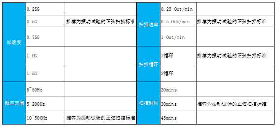
The sine test is divided into two types of tests: linear scanning and logarithmic scanning. Generally, linear scanning is more suitable for resonance frequency search, and logarithmic scanning is more suitable for fatigue durability. At present, the vast majority of enterprises conduct experiments using logarithmic scanning. The following are standard recommended values:
Constant frequency test
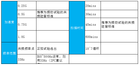
It depends on the ability of the test piece to adapt to long-term resonant environments.
Find the resonance vibration point from the sine sweep frequency, analyze it, and select the maximum resonance vibration point or frequency point with more occurrences as the dwell point.
Random vibration test
For most vibration environments, natural or artificially generated vibrations are mostly random waves. The vibrations generated by waves, tidal currents, winds, earthquakes, and the entire transportation process of products are all random vibrations. If the random vibration environment encountered by the actual product can be simulated in the vibration test, then the sample can be verified using random vibration. The testing efficiency is much higher than that of sinusoidal vibration, and it is not prone to adverse effects such as excessive stress or residual stress generated by sinusoidal scanning.
The source of spectral values for random vibration tests is obtained through the integration of a large amount of data and the collection of many spectral data paths. In actual transportation scenarios, there are not only vibration data, but also many other mechanical stress scenarios. Therefore, separating and distinguishing from the collected data alone is a complex and cumbersome task.
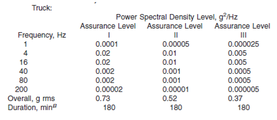
The following figure shows the recommended random vibration spectrum of ASTM4169-14.
3.5.2 Collision Impact
collision
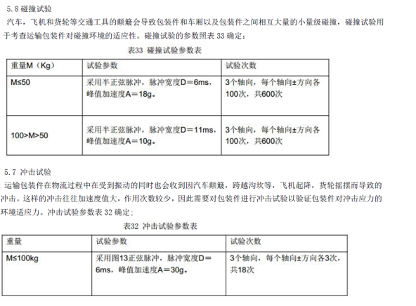
Repeated and low severity impact phenomena often encountered during transportation and use of samples. The damage to the sample caused by collision tests mainly manifests as cumulative damage.
If general products are shipped to developing countries, or areas with low urbanization and poor transportation conditions, collision is a strong test that needs to be conducted.
failure mechanism
When the product is subjected to continuous collision, it can refer to the low cycle fatigue of the material. During each collision process, the packaging or product will deform, and once it accumulates to a certain level, it will cause qualitative change, leading to packaging or product failure.
General failure: Cracking or detachment of circuit board components, structural deformation or cracking of products, and packaging damage.
Impact
Mainly simulate the impact phenomenon of high severity level that occurs accidentally and does not repeat during transportation and use of the sample. The damage to the sample during impact testing mainly manifests as strength damage.
When a product falls or collides, impact stress will be generated, which may cause damage to the structure of the product. It can be in two cases: products with packaging and without packaging. The most typical one is the half sine wave.
The impact test has the greatest impact on the product in terms of structural strength. During the test, structural fractures and solder cracks often occur.
failure mechanism
When a product is impacted, its motion state will undergo sudden changes and generate transient responses. Its response is a high-frequency oscillation, short period, and high-energy wave with significant rise and fall. If the amplitude of the impact response exceeds the strength of the product, it will cause damage to the product.
General failure: Cracking or detachment of circuit board components, structural deformation or cracking of products, material damage at physical limits.
Test standards
The main standards for impact testing include IEC 60068-2-27 (GB/T 2423.5), IEC 60068-2-29 (GB/T 2423.6), MIL-STD-883G, EIA-364-27B, etc.
3.5.3 Drop
There are many potential drops throughout the entire lifecycle, including during packaging and transportation, as well as during use after reaching customers. This requires us to conduct drop tests on both the packaging and bare machine of the product to ensure that it has a certain level of anti drop ability.
We often see violent sorting by express delivery companies, from the center to the unloading point to the scattered point before scanning out of the warehouse. A package needs to be thrown at least three times, which is the process of extreme packaging falling.
failure mechanism
When the packaging or product falls, it will collide with the ground, causing deformation of the packaging or product. After deformation to a certain extent, it may rebound, but when it reaches the limit of damage, it will directly break and cannot rebound. If the collision level exceeds the strength of the product, it will cause damage to the product. Drop is a strong impact that verifies whether the product's limit has been exceeded at this drop height.
Drop failure generally includes cracking or detachment of circuit board components, structural deformation or cracking of products, and packaging damage.
Test standards
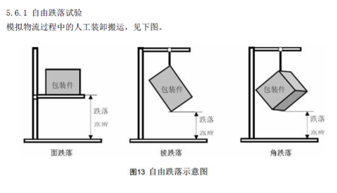
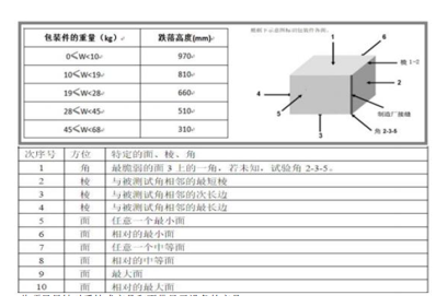
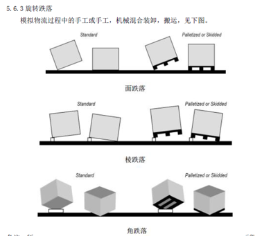
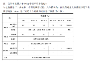
The drop test standards include ISTA series GB/T 4857.5IEC 60068-2-32 (GB/T2423.8) MIL-STD-810G Method 516, among which free drop and rotational drop are shown in the following figure for example.
3.5.4 Earthquake
Earthquakes, also known as earthquakes or vibrations, are natural phenomena caused by the rapid release of energy from the Earth's crust, during which seismic waves are generated. The main cause of earthquakes is the mutual compression and collision between plates on Earth, which causes dislocation and rupture along the edges and inside the plates.
During an earthquake, the most basic phenomenon is the continuous vibration of the ground, mainly characterized by obvious shaking. People in extreme earthquake areas sometimes feel a jump up and down before feeling a big shake. Because seismic waves travel from the ground to the ground, longitudinal waves arrive first. The shear wave then generates large amplitude horizontal shaking, which is the main cause of earthquake disasters. Therefore, vibration spectra are usually used to simulate earthquake tests.
In recent years, earthquakes have occurred frequently both domestically and internationally, causing great losses to people's lives and property safety. Often, after earthquakes, equipment in disaster areas, especially communication systems, will be damaged to a certain extent. However, the quality of post earthquake communication systems will greatly affect the timeliness and pertinence of post earthquake rescue and life and property. Therefore, in the standards for communication equipment at home and abroad, There are relevant regulations and test requirements for the seismic resistance of communication equipment.
failure mechanism
Direct disasters caused by earthquakes are the primary phenomena of earthquakes, such as fault displacement and ground vibrations caused by seismic waves. Mainly including: damage to the ground, damage to buildings and structures, damage to natural objects such as mountains (such as landslides, mudslides, etc.), tsunamis, ground burns, etc.
The failure mechanism of earthquakes is similar to that of vibration, and the impact on electronic equipment is mainly structural damage, which can be divided into permanent structural damage and recoverable structural damage.
Permanent structural damage is defined as the deformation of any load-bearing component, failure of components and any connecting components, typical examples of which are bending or cracking of equipment cabinet columns, deformation or cracking of bases, fracture or cracking of fasteners, etc; Recoverable structural damage is defined as the misalignment or separation of components that can function normally after restoration. Typical examples include circuit board and module detachment, drawer or lid opening, door opening, etc.
Test standards
The test standards for earthquakes include GR63/EN300 019/GB5083, etc. The following are examples of GR63 earthquake test conditions.
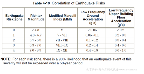
Earthquake intensity at different regional levels
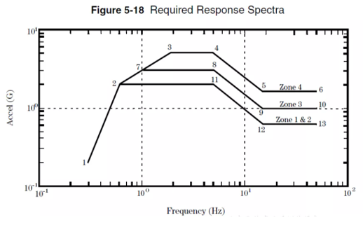
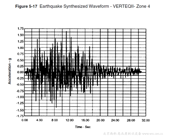
Conduct seismic testing on the equipment using the specified waveform for testing. The acceleration time waveform shown in Figures 5-17, VERTEQII, synthesizes several typical earthquake scenarios that are applicable to different buildings and soil conditions. The testing steps of the equipment should be carried out according to the motion specified by the synthesized waveform generated on the vibration table.
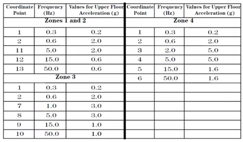
Figures 5-18 show the vibration spectra of four different seismic zones in different regions.
